The SI430 serial interface has 8 analog input channels that can measure 0 to +5 Vdc with 10 bits of resolution. To detect real-world phenomona, a sensor must be connected so that a signal is received at the SI430 input that is between 0 and +5 Vdc, and reflects the output of the sensor. This project describes how to interface resistive-type sensors to the SI430 for use with Channel 8.
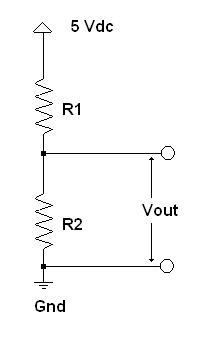
The half-bridge circuit allows a change in resistance to create a change in voltage, as shown below.
Here is the equation for a half-bridge circuit: Vout = (+5 Vdc * R2)/(R1 + R2).
To take a simple example, for R1 = R2 = 1000 Ohms, Vout = (5 * 1000)/(1000 + 1000) = 2.5 Vdc. This makes perfect sense because if there is a 5 Vdc drop across both resistors to ground, and the resistors are of equal value, then the point at which the resistors join in the half-bridge must be halfway in potential between +5 V and 0 Vdc (Gnd).
To take another example, if R1 = 1000 Ohms and R2 = 4000 Ohms, Vout = (5 * 4000)/(1000 + 4000) = 4.0 Vdc. As before, 20% of the total voltage drop is over the 1K resistance and 80% over the 4K resistance.
So if you had a sensor that varied in resistance from 1K to 4K, you could wire it as R2 in a half-bridge circuit (where R1 is 1K) and expect that the voltage input to the SI430 would range between 2.5 and 4 Vdc, depending on the resistance of the sensor.
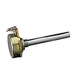
Potentiometers can come in all sorts of styles, but the most familiar is the simple volume control used on older radios and stereo equipment (See photo below). This sort of potentiometer can be used to convert rotary angle or position into a voltage output that can be sensed by the SI430. The pot typically has 270 degrees of rotation on its shaft, which can be connected to a rotating object to sense angular position.
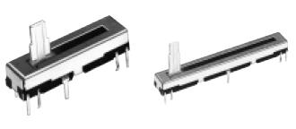
Another style of potentiometer position sensor is a slider pot, as shown below. The wiper moves in a straight line, so this style potentiometer can be used to sense linear displacement and position.
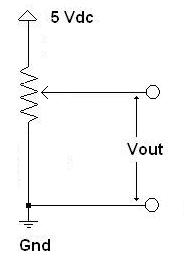
For any type of potentiometer connected to the SI430 +5 Vdc supply, its full travel will result in a change of voltage from 0 to +5 Vdc allowing the greatest resolution for the SI430 analog inputs. One consideration when selecting a potentiometer type sensor is its nominal resistance. Because the pot is wired across the full +5 V supply, be sure that its nominal overall resistance is at least 10K so that only a few mA of current passes through each sensor connected. Remember, if you connect 8 sensors, the load on the power supply is increased 8 times over just a single sensor. But a 10K nominal resistance is usually sufficient to avoid problems.
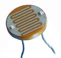
Once you know its resistance change, a photocell can be wired into a half-bridge configuration using a fixed resistance, as shown below.
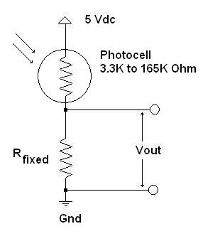
The value of the fixed resistance, Rfixed, must be calculated to provide the greatest possible output voltage change over the changes in resistance for the photocell. This is an iterative process, and putting the voltage divider equation into a spreadsheet and solving for various light levels and values of Rfixed will eventuially result in an optimal value.
For example, with a value of 20K Ohms for Rfixed the circuit will produce a voltage output of 4.29 Vdc when the photocell is in bright light and an output of 0.54 Vdc when the photocell is in the dark. This is a swing of 3.75 Vdc and will provide sufficient sensitivity for the SI430 to detect even small changes in ambient light levels. Once you get the circuit working, simply record the voltage readings under various lighting condtions. There is no quantitative calibration, but the readings can be surprisingly useful.
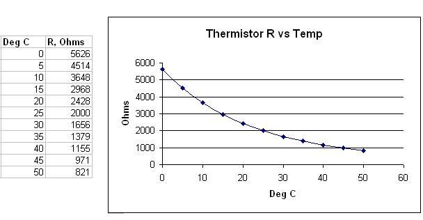
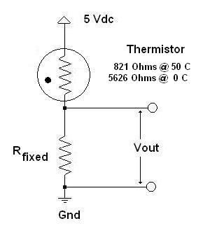
Once again, a spreadsheet is a good way to determine the optimal value of Rfixed in the thermistor half-bridge. For the example thermistor curve shown above, a value of 5K Ohms for Rfixed produces 2.353 V at 0 Deg C and 4.295 Vdc at 50 deg C. A 5K fixed resistance will keep the current through the thermistor to just a few mA; thermistors can self-heat and this can cause measurement errors. In this case, with a voltage swing of 1.95 Vdc from 0 to 50 C allows the SI430 to detect temperature changes less than 0.2 deg C.
Determining the actual temperature is a more complicated issue. As can be seen from the voltage output graph (generated in a spreadsheet), the signal is not linear with temperature.
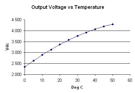
One way to determine temperature from voltage would be to fit a second or third order equation to the curve. The coefficients of the curve would be applied to the incoming voltage data. The thermistor has an accuracy of 1 deg C, so a curve could probably be devised to achieve a fit close enough to support that level of precision. A second method, perhaps more straightforward to implement, is to divide the curve into a series of segments and do a linear interpolation between the known points. In either case, Perl could do the necessary math after receiving the voltage reading from the SI430.
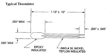
There are a number of other temperature sensors available, but these are generally not suitable for interface directly to the SI430. A thermocouple produces a very small voltage signal, just a few mV over hundreds of degrees, and would need amplification. Semiconductor sensors are generally built around the voltage drop across a diode, and this is typically just a few mV. RTD sensors change resistance linearly with temperature, but the resistance change is fairly small; just a couple hundred Ohms over several hundred degrees. Thermistors, with all of their complications, are probably the best combination of accuracy, sensitivity and low cost for use with the SI430.
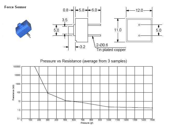
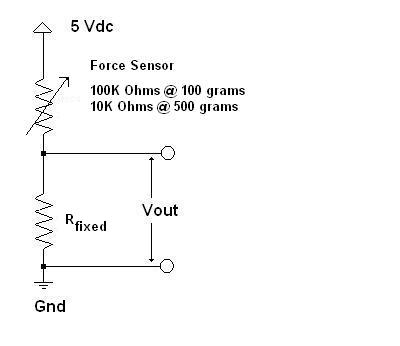
This device may be wired in a half-bridge, and a value of 5K Ohms for Rfixed will produce a voltage of 0.23 Vdc with zero force and 1.67 Vdc with a force of 500 grams applied to the button. The output is highly non-linear, so a lot of computations and curve-fitting would be required to produce an actual force measurement. The device is probably not very repeatable, so any effort spent in mathmatically characterizing its output as a function of applied force might ultimately be misspent. But it can be used to sense a force limit, given a reasonable tolerance, and could be used to detect, say, an over weight condition or something similar.
By itself, the SI430 is insufficient for use with more transditional force sensors such as strain gages or load cells. These devices are highly linear and much more precise (as well as much more expensive). But the output of the typical load cell is just 10 mV over its entire range when powered by 5 Vdc and this requires amplification. Another idea to measure weight would be to make a spring scale and measure its displacement with a potentiometer as a function of weight.
There are similar pressure sensors that have low level outputs of 100 mV or so at full scale. These would not be suitable for direct connection to the SI430 without amplification. Always keep in mind that the resolution of the SI430 is 1024 counts over +5 V of signal input. When the signal is limited by the sensor to just a few millivolts, the SI430 will not have enough resolution to give a good reading.